Basic Circuit Elements: Resistors, Inductors, and Capacitors
Basic Circuit Elements:
Resistors, Inductors, and Capacitors
Introduction
In the realm of electronics, understanding the
fundamental building blocks is essential. These elements—resistors, inductors,
and capacitors—are critical for controlling and managing electric
current and voltage within circuits. Every electronic device, from simple
flashlights to complex smartphones, relies on these components. In this
comprehensive guide, we will explore the characteristics, functions, and real-world
applications of these basic circuit elements.
Resistor
1.1 Definition
A resistor is a passive electronic component
designed to resist the flow of electrical current. Its main purpose is to limit
the amount of current flowing through a circuit, which prevents components from
being damaged by excessive current.
1.2 Symbol

- Resistance
(R): Resistance is the property of a material that
opposes the flow of current. It is measured in ohms (Ω).
- Ohm’s Law: The relationship between voltage, current, and resistance is given by Ohm’s Law: V=IR , Where:
- V is the voltage across the resistor
(volts),
- I is the current through the resistor
(amperes),
- R is the resistance (ohms).
- Power
Dissipation: When current flows through a resistor, it
dissipates energy in the form of heat. The power dissipated by a resistor
is given by: P=IV
1.4 Types of Resistors
- Carbon
Composition Resistors: Common and inexpensive, these resistors are
made of carbon particles and a binder. They are used in general-purpose
applications.
- Wire-Wound
Resistors: Constructed by winding a resistive wire
around a ceramic core. These resistors handle high power and offer precise
resistance values.
- Metal
Film Resistors: Provide low noise and precise resistance
values. They are used in high-performance applications.
- Variable
Resistors (Potentiometers): Allow users to manually
adjust resistance. These are commonly used in devices like volume controls
and tuning circuits.
1.5 Resistor Color Code
Resistors often use a color code to represent their
resistance value. For example, a resistor with color bands of brown, black, and
red has a resistance of 1kΩ.
Diagram Suggestion: Include
an image showing a resistor with color bands and explain how to decode the
resistance value using the color code chart.
1.6 Resistors in Series and
Parallel
- Series Connection: When resistors are connected end-to-end, the total resistance is the sum of the individual resistances:
- Parallel Connection: When resistors are connected in parallel, the total resistance decreases. The formula for parallel resistance is:

1.7 Applications of Resistors
- Current
Limiting: Used to limit the current flow in a circuit,
ensuring that sensitive components do not get damaged.
- Voltage
Division: In voltage divider circuits, resistors split
an input voltage into smaller, more manageable values.
- Biasing
Components: Resistors help set the correct operating
point for transistors and other active devices.
Example: In a simple circuit with a power
supply, resistor, and LED, the resistor limits the current, protecting the LED
from damage.
Diagram Suggestion: Include
a diagram of a voltage divider and a simple series circuit with a resistor and
LED.
Inductor
2.1 Definition
An inductor is a passive electronic
component that stores energy in a magnetic field when current flows through it.
Inductors resist changes in current, making them useful in filtering and energy
storage applications.
2.2 Symbol

- Inductance
(L): The ability of an inductor to store energy is
called inductance, measured in henries (H). The inductance of a
coil depends on the number of turns, the core material, and the coil's
dimensions.
- Self-Inductance:
When a changing current flows through an inductor, it generates a magnetic
field that opposes the change in current. This phenomenon is known as self-inductance.
- Time Constant: The time constant of an RL (Resistor-Inductor) circuit determines how long it takes for the current to stabilize. The time constant is calculated as:

- Air-Core
Inductors: These inductors do not have a core and are
used in high-frequency applications.
- Iron-Core
Inductors: Use a core made of iron or steel, which
increases inductance and allows the inductor to handle higher currents.
- Toroidal
Inductors: These inductors are wound around a
donut-shaped core, which minimizes electromagnetic interference (EMI).
2.5 Inductors in Series and
Parallel
- Series Inductors: The total inductance is the sum of individual inductances:
- Parallel Inductors: The reciprocal of the total inductance is the sum of the reciprocals of individual inductances:

- Filters:
Inductors are used in LC (Inductor-Capacitor) circuits to filter out
unwanted frequencies from signals.
- Energy
Storage: Inductors store energy in magnetic fields and
are used in devices like transformers and DC-DC converters.
- Chokes:
Inductors block high-frequency AC signals while allowing DC or
low-frequency signals to pass.
Example: In a power supply circuit, an
inductor is used to filter out high-frequency noise from the output.
Diagram Suggestion: Include
an LC filter diagram showing an inductor paired with a capacitor to filter
signals.
Capacitor
3.1 Definition
A capacitor is a passive component that
stores electrical energy in an electric field. It consists of two conductive
plates separated by a dielectric material. Capacitors are used to block direct
current (DC) while allowing alternating current (AC) to pass, store energy, and
filter signals.
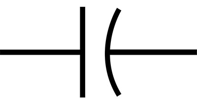
3.2 Symbol
| Image | Capacitor symbol | Type |
|---|---|---|
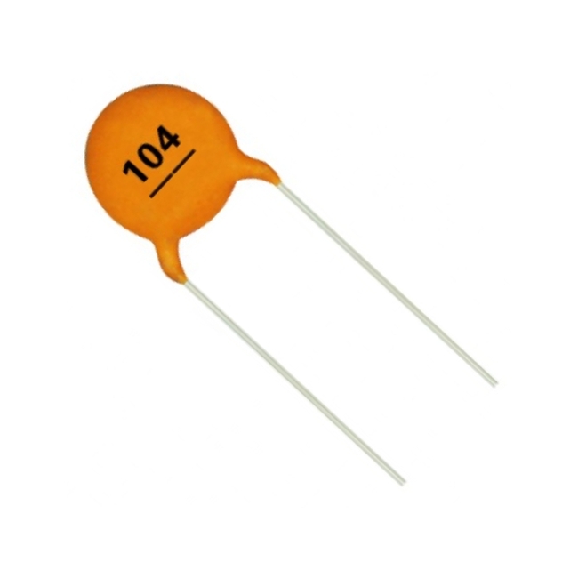 |  | Disc ceramic Capacitor |
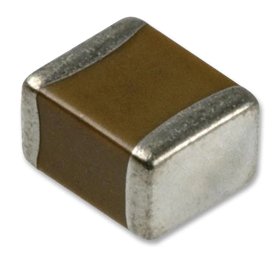 |  | Multilayer Ceramic Capacitor (MLCC) |
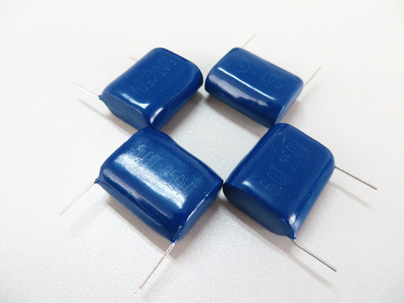 |  | Metalized Film Capacitor |
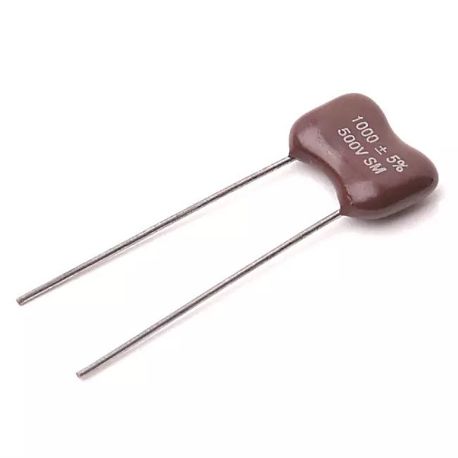 |  | Mica Capacitor |
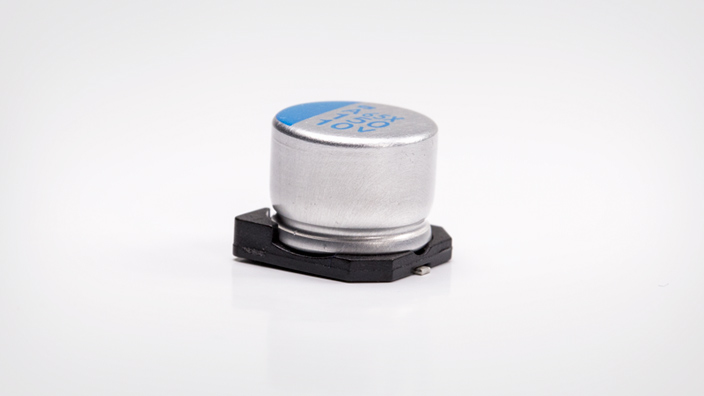
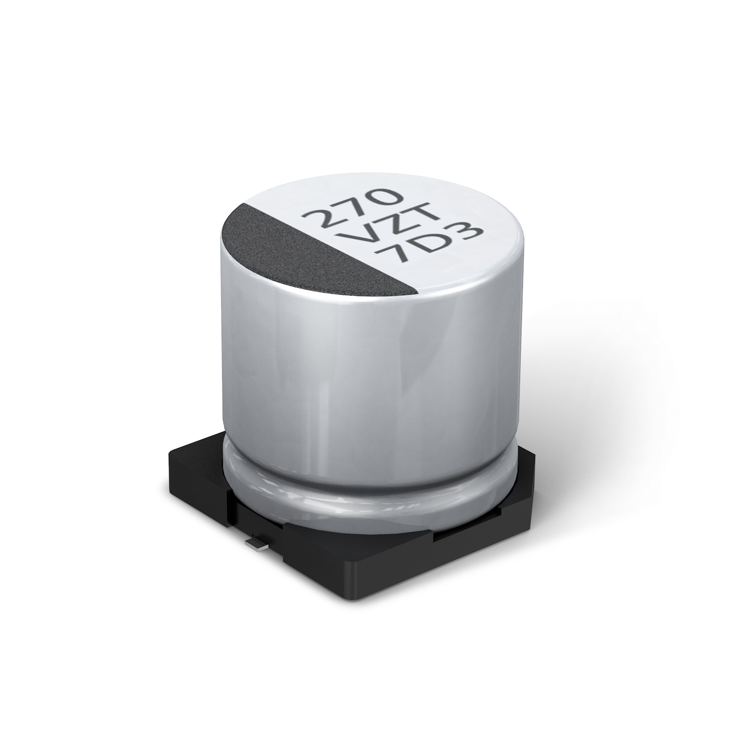 |  | Aluminum Electrolytic Capacitor |
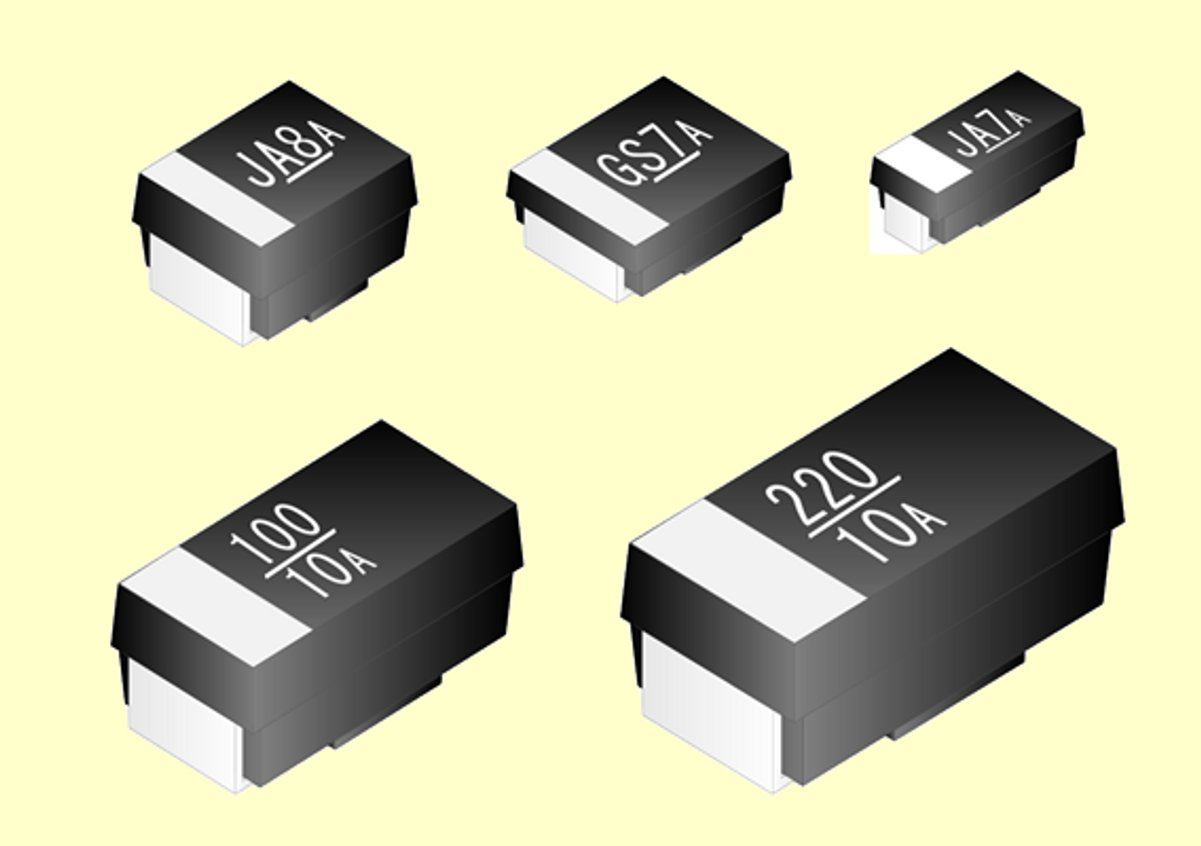
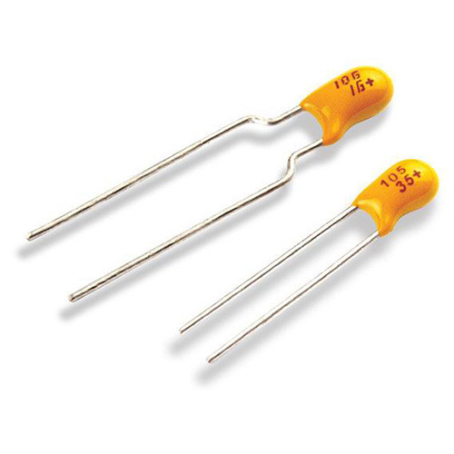 |  | Tantalum Electrolytic capacitor |
 |  | Niobium Electrolytic Capacitor |
 |  | Aluminum Polymer Capacitor |
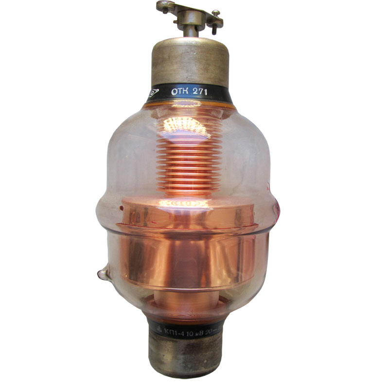 |  | Variable Vacuum Capacitor |
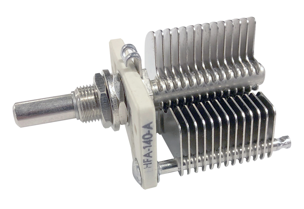 |  | Variable Air Gap Capacitor |
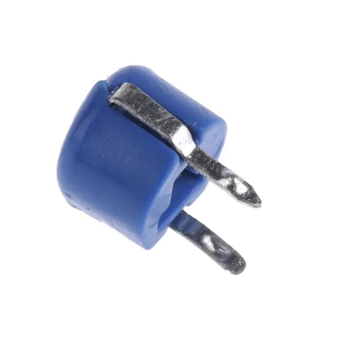 |  | Ceramic Trimmer Capacitor |
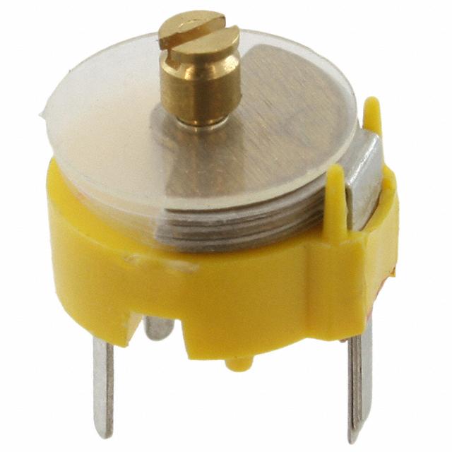 |  | Film Trimmer Capacitor |
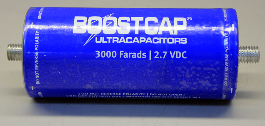 |  | Supercapacitor |
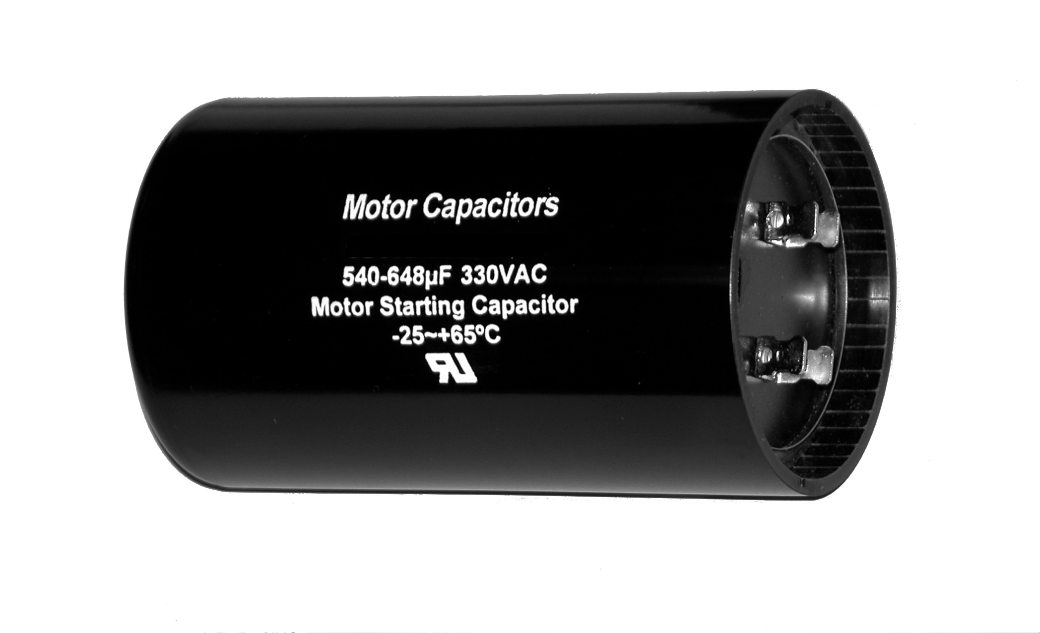 |  | Motor Run and Start Capacitor |
3.3 Characteristics
- Capacitance
(C): The ability of a capacitor to store charge is
called capacitance, measured in farads (F). The capacitance depends
on the surface area of the plates, the distance between them, and the
dielectric material used.
- Charging
and Discharging: When a voltage is applied across the
terminals of a capacitor, it stores energy. The voltage across the capacitor
changes over time, following an exponential curve.
- Time Constant: The time constant in an RC (Resistor-Capacitor) circuit is the time it takes for the voltage to reach 63% of its final value. It is calculated as: τ=RC
3.4 Types of Capacitors
- Ceramic
Capacitors: Small, inexpensive capacitors used in
high-frequency applications such as radio frequency (RF) circuits.
- Electrolytic
Capacitors: Polarized capacitors with high capacitance
values. They are used for energy storage and filtering in power supplies.
- Film
Capacitors: Stable, low-leakage capacitors used in
applications requiring precision.
3.5 Capacitors in Series and
Parallel
- Series Capacitors: The total capacitance decreases in a series configuration:

- Parallel Capacitors: The total capacitance increases in parallel:
- Energy
Storage: Capacitors store electrical energy for quick
discharge in devices like camera flashes and defibrillators.
- Filtering:
Capacitors are used to filter out unwanted signals in audio and power
circuits.
- Coupling
and Decoupling: In AC circuits, capacitors allow the passage
of AC signals while blocking DC.
Example: In a power supply circuit,
capacitors are used to smooth out voltage fluctuations.
Diagram Suggestion: Show a
circuit where capacitors are used to filter AC signals or smooth voltage in a
power supply.
Combination of Resistors,
Inductors, and Capacitors
By combining resistors, inductors, and capacitors
(RLC circuits), engineers create filters, oscillators, and resonant circuits
that are essential in communication, audio, and RF systems. Some common
configurations include:
- RC
Circuits: These circuits are used in audio filtering
and timing applications.
- RL
Circuits: Used to smooth power supplies and in motor
control circuits.
- RLC
Circuits: Used in resonant circuits, which are vital in
radio receivers and transmitters.
Comparison: Resistor vs Inductor vs Capacitor
|
Property |
Resistor |
Inductor |
Capacitor |
|
Function |
Limits current |
Stores energy in a magnetic field |
Stores energy in an electric field |
|
Unit of Measure |
Ohms (Ω) |
Henry (H) |
Farads (F) |
|
Symbol |
(Show resistor symbol) |
(Show inductor symbol) |
(Show capacitor symbol) |
Conclusion
Resistors, inductors, and capacitors are the
cornerstones of electronic circuits. Their distinct properties and functions
allow them to shape the behavior of current and voltage in various ways,
enabling the creation of a vast array of electronic devices. Understanding how
these components work individually and together in circuits is key to mastering
the art of electronics. Whether you're designing a simple LED circuit or a
complex communication system, resistors, inductors, and capacitors will always
play a vital role.
FAQs: Resistors, Inductors, and Capacitors
Q1: What is the primary function of a resistor in an electronic circuit?
A: The primary function of a resistor is to limit or control the flow of electric current. Resistors can reduce current, divide voltage, and protect components from damage due to excessive current.
Q2: How is the value of resistance measured and represented?
A: Resistance is measured in ohms (Ω). It is often represented using color codes on resistors. For example, a resistor with bands of brown, black, and red indicates a resistance of 1 kΩ (1000 ohms).
Q3: What happens when resistors are connected in series or parallel?
A:
- Series Connection: When resistors are connected in series, their total resistance increases. The total resistance is the sum of individual resistances.
- Parallel Connection: When resistors are connected in parallel, the total resistance decreases. The reciprocal of the total resistance is the sum of the reciprocals of the individual resistances.
Q4: What is an inductor used for in electronic circuits?
A: Inductors are used to store energy in a magnetic field when current flows through them. They are often used in filters, transformers, and energy storage applications. Inductors resist changes in current, making them useful for smoothing voltage and current in circuits.
Q5: How does an inductor differ from a capacitor?
A:
- Inductor: Stores energy in a magnetic field and opposes changes in current.
- Capacitor: Stores energy in an electric field and opposes changes in voltage.
Q6: What is the role of a capacitor in a circuit?
A: Capacitors are used to store and release energy. They block DC (direct current) and allow AC (alternating current) to pass, making them crucial in filtering, signal coupling, and timing applications. They also smooth out voltage fluctuations in power supplies.
Q7: What is the time constant of a capacitor and why is it important?
A: The time constant of a capacitor is the time it takes for the voltage across it to reach 63.2% of its final value during charging or discharging. It’s important in timing circuits, as it helps determine how fast a capacitor charges or discharges.
Q8: How do capacitors behave when connected in series and parallel?
A:
- Series Connection: When capacitors are connected in series, the total capacitance decreases. The reciprocal of the total capacitance is the sum of the reciprocals of individual capacitances.
- Parallel Connection: When capacitors are connected in parallel, the total capacitance increases. The total capacitance is the sum of the individual capacitances.
Q9: What are common applications of resistors, inductors, and capacitors?
A:
- Resistors: Used in voltage dividers, current limiting, and biasing circuits.
- Inductors: Used in filters, transformers, and DC-DC converters.
- Capacitors: Used in power supply smoothing, signal coupling, and oscillators.
Q10: Can resistors, inductors, and capacitors be used together?
A: Yes, combining resistors, inductors, and capacitors creates RLC circuits, which are used in filters, oscillators, and resonant circuits. These combinations are essential in radio, audio, and communication systems.
Q11: What is an RC circuit, and where is it used?
A: An RC circuit is a combination of a resistor and a capacitor. It is commonly used in timing circuits, filters, and oscillators. RC circuits are used to filter signals or create delays in electronic systems.
Q12: How do inductors affect the current in a circuit?
A: Inductors resist changes in current. When the current through an inductor changes, it generates a voltage that opposes the change, which slows down the rate of current change in the circuit. This property is why inductors are commonly used in filters and power supply circuits.
Q13: Why are electrolytic capacitors polarized, and how should they be connected?
A: Electrolytic capacitors are polarized because they use an electrolyte as a dielectric, which must be connected with the correct polarity (positive and negative terminals). Connecting them backward can damage the capacitor or the circuit.
Q14: What are variable resistors, and what are they used for?
A: Variable resistors (or potentiometers) allow the resistance to be manually adjusted. They are commonly used in applications like volume controls in audio systems or for adjusting brightness in displays.
Q15: Can resistors, capacitors, and inductors be used to create filters?
A: Yes, combining these elements allows you to create low-pass, high-pass, band-pass, and band-stop filters that control the frequency response of signals in communication, audio, and signal processing applications.
"This Content Sponsored by Genreviews.Online
Genreviews.online is One of the Review Portal Site
Website Link: https://genreviews.online/
Sponsor Content: #genreviews.online, #genreviews, #productreviews, #bestreviews, #reviewportal"

Comments
Post a Comment